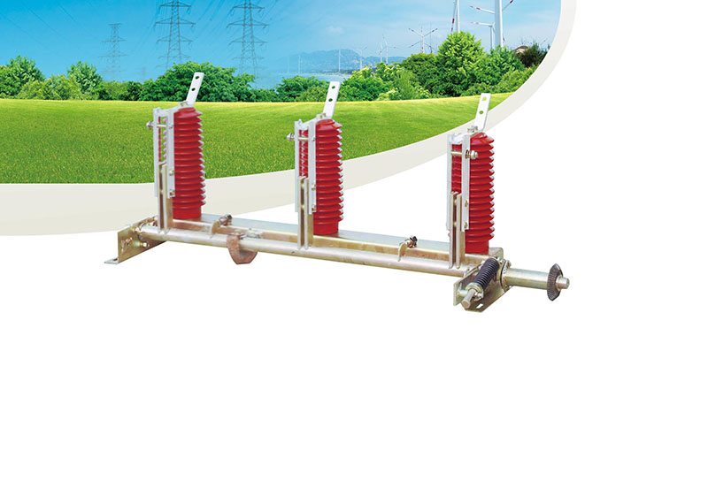
TJN2-40.5 Indoor high voltage grounding switch
Outline
TJN2-40.5 type indoor high voltage grounding switch is designed as the high voltage household appliances by being equivalent to adopt IEC129-84 Isolation Switch and Grounding Switch and IEC694-84 Common Clause of High Voltage Switchgear and Control Equipment, according to the part of grounding switch of GB1985-89 AC High Voltage Isolator and Grounding Switch.
TJN2-40.5 grounding switch is suitable for power system of 35KV and below three-phase AC 50Hz, and has voltage monitoring device. Its structure is simple and reliable, operation force is small, installation and debugging is convenient. It is usually used in TJYN1-40.5 and TGFC-40.5 switchgear, and can also be used separately.
Environmental condition
Ambient air temperature: upper limit 40 ℃, lower limit -10 ℃, high cold region -25 ℃. Note: allow storage and transportation at-30 ℃.
The altitude does not exceed 1000 m.
Relative humidity: the daily average is not greater than 95 and the monthly average is not greater than 90.
The seismic intensity does not exceed 8 degrees.
Places free of fire, explosion hazards, severe contamination, chemical corrosion and violent vibration. Note: if the conditions of use of the product exceed the above-mentioned regulations, the user and the manufacturer shall negotiate.
Outline overall and installing dimensions
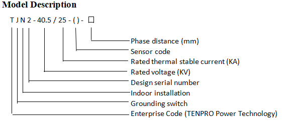
TJN2-40.5/25-□ TJN2-40.5/25(WQ)口
Main technical parameters
|
Serial No. |
Item |
Unit |
Parameter |
Item |
|
1 |
rated voltage |
KV |
40.5 |
|
|
2 |
4s thermal stable current (RMS) |
KA |
25 |
|
|
3 |
Dynamic stable current (peak) |
KA |
63 |
|
|
4 |
Closing short circuit current (peak) |
KA |
63 |
|
|
5 |
Rated insulation level |
KV |
185 |
|
|
95 |
Lightning impulse withstand voltage |
|||
|
2 |
Main circuit loop 1min power frequency withstand voltage |
|||
|
6 |
Partial discharge of Voltage display device |
PC |
≯10 |
Secondary circuit loop 1min power frequency withstand voltage |
Note: TJN2-40.5 / 25-□ ordinary insulator without display device; TJN2-40.5 / 25- (WQ)-□ passive epoxy full working condition insulator sensor with DXN□-40.5/□
Structure and working principle
The operating system of the grounding switch is designed in the form of spring energy storage, and has the ability of fast closing. When the operating link is closed, it drives the gear on the grounding switch, so that the spindle rotates to the closing side, and the spring is compressed for energy storage. To a certain position (when the spindle starts to move 30 °above the center line from the lower limit) the spring energy is released and the fast closing is made. At this time, the closing speed is independent of the operator’s action, and this structure ensures that the grounding switch has the required closing capacity.
Similarly, when the switch is opened, the operating link drives the gear on the grounding switch, which rotates along the opening direction, and the spring device stores energy. When the rotation angle of the main shaft exceeds 45 °, the spring energy storage device releases energy and makes the grounding switch close.
According to the requirements of users, the grounding switch can be configured with different types of high voltage live display device. The supporting post insulators can be selected from epoxy insulators or DXN passive live display devices. Please refer to the installation instructions for the high-voltage live display device for the content of the display device.


